Add/Edit/Delete a dynamic link between an alignment and selected pipe network's structures
| Command: IMAddNetworkAlignmentLink |
|
 |
With the start of the command a window opens for you to create the link.
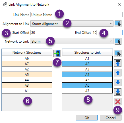
- As you can have multiple links created within a drawing, each link needs to have a unique name. If you
prefer, the software will name it for you using the format [Alignment Name] > [Network Name] and will add a number
if needed to make it unique.
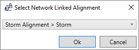
- Select the alignment from the list. Optionally, you can graphicaly select the alignment from the drawing.
The alignment selected will be the one that dynamically updates if there are any changes to the structure locations.
- Optionally, you can set the alignment's start to be offset from the first structure. The first alignment segment will
be extended by the amount entered. The software will still keep the first structure as the start station reference point
of the alignment.
- Similar to the start offset, you can set the alignment's end to be offset from the last structure. The last alignment segment will
be extended by the amount entered.
- Select the pipe network from the list. Optionally, you can graphicaly select the pipe network from the drawing by selecting
in plan view either a pipe or structure that belongs to the network. The network selected is the one whose selected structure's will
be linked to the alignment.
- This list shows ALL the structures belonging to the pipe network.
- Use this button to copy the structure from the pipe network list to the linked structures list
- This list shows the pipe network's structures that are linked to the alignment.
- The order of the linked structures is important. The top structure is the start point for the alignment. Working through the list
in order to the bottom of the list as the end of the alignment. Use the buttons here to control the order or even remove a structure from
being linked.
Select OK to create (or edit) the link and close the window.
|
 NetworkAlignmentLinks

